Assignment 4: Hinge

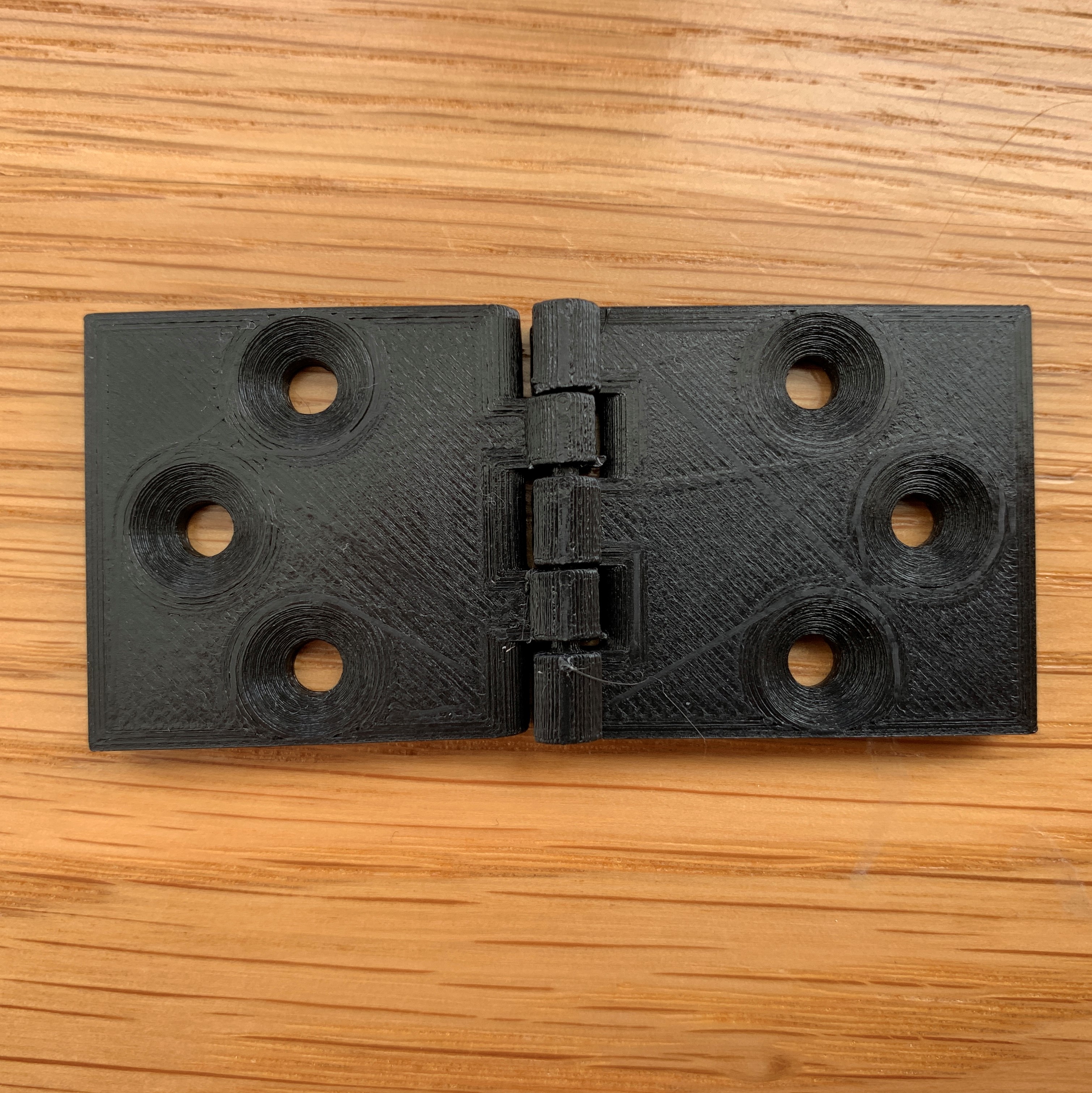
I decided for this assignment that I wanted to make a hinge - and I thought it would be fun to try to 3D print the entire hinge in one piece... no assembly required!
Here's the link to the Onshape file.
First, I started by designing the hinge on paper. I watned it to have 6 screw holes - 3 on each side - and 3 knuckles.
I started in Onshape by creating a sketch for the male leaf. I decided to create the lower half of it and then mirror it vertically to complete the design. I created a rectangle, a circle for screws (measured for a standard M5 screw with 4mm drill size), and a half-circle (that would be reflected into a full cicle) for another screw.

Once I had that part done, I extruded it to be 5mm tall.
Then, I made the sketch for the knuckle. This evolved over the course of the design but it started as a rectangle with a half-circle on top.
I extruded the knuckle to extend all the way to the end of the leaf - I had to use "Add" rather than "New" otherwise I had intersection issues.
Then I needed to cut out notches / knuckles. I made a sketch for that (simple rectangle) and used Extrude to remove it - I used "Remove" and "Solid" as the settings.
After that, I needed to make the pin that the hinge would rotate around. I did that with a circle that I extruded all the way from one end of the leaf to the other (using "Add" and "Solid" as the settings).
Then it was time to mirror the leaf so it took on the full shape. I used "Reflect" to do that.
Next I created the female leaf, following the same process for the beginning of the male leaf.
Once I had the female knuckle though, I needed to extrude it from the end of the 1st male knuckle to the beginning of the 2nd male knuckle - so I could eventually create a gap in between them and prevent fusion. I used "Second End Position" in Extrude and it allowed me to do that successfully.
Then I reflected the leaf so it matched the other one.
Next I wanted to chamfer the screw holes, so I used a distance of 2.5mm and a 45* angle, based on some resources I found online about the design of the M5 screws.
I did all the initial work with no tolerances/wiggle room, which obviously would have posed a problem when I 3D printed it, as everything would be fused together.
So, I needed to adjust the openings between all the parts so I started by bringing everything .2mm apart. I also had to redesign the knuckles a bit just to make them line up correctly after being shifted around.
I also filleted the edge of the female leaf closest to the knuckle so it would be a smoother motion.
I tested my design by creating an assembly and adding a revolute mate.
Then it was time to print!
I used the following settings, which gave me a *tiny* bit of support material inside the hinge that should be easy to break apart.

I ran a print but after the first layer it was clear that the parts were going to be all fused together.
I went back to the Onshape file and adjusted the gaps to be .4mm. Printed again but after a few layers it still seemed too tight.
.6mm gaps seemed to do the trick.
However I had a snapping issue so I had to thicken up the wall of the hinge a bit by making the pin and pin hole smaller.
I printed again and was able to get the hingle moving, which was great!
The small amount of support material inside the hinge broke easily.
But the hinge didn't go all the way closed. I realized I needed to fillet the other side, so I filleted the male leaf on the side closes to the pin.
Printed again and it worked great! Now I have an awesome and smooth hinge.
Thanks to Josh for the helpful tutorial on using Onshape and Hannah N. for helping me figure out how to publically share the link to the Onshape file!